
ECE Design Lab
The Duke ECE Design Lab is located at 113B Hudson Hall. The lab contains two hot air SMD Rework Stations from Weller. Both stations can perform conventional through-hole soldering and newer SMT soldering. The stations allow for quick and simple IC attachment and detachment through the use of solder paste and the hot air tool.
In addition to the soldering stations, the Design Lab features a mini-reflow oven that can solder an entire board at once through the oven reflow process. In contrast to the expensive (and very large) conventional reflow ovens used in industry, the Design Lab utilizes a Cuisinart toaster oven to model an appropriate thermoprofile for the reflow of the solder paste. Many students enrolled in ECE Design courses such as ECE 459 Embedded Systems (F) and ECE 449 Sensors & Sensor Interface Design (S) have utilized the oven successfully to complete their final boards.
The ECE Design Lab also provides in-house Printed Circuit Board etching capabilities. Although it is often easier and less expensive to order a printed circuit board for a project design from a reliable manufacturer (Advanced Circuits (use “Student Special”, $33 per board), PCB Fab Express, Express PCB, and others …) , for smaller, typically surface-mount only designs this do-it-yourself approach is a useful technology.
Early on, the ECE Design Lab added the capability to 3D print, making it one of the first labs at Duke to have 3D printing capability. A MakerBot Replicator 2 3D printer is still available with permission in the laboratory. The 3D printer greatly expands the possibilities for enclosing final project circuits in compact, customized boxes and housings. Examples of 3D printed objects are available to view in the laboratory. The Technology Engagement Center Co-Lab has now become the best go-to resource for 3D printing in engineering.
Please stop by for a demonstration, tour of the lab, or assistance—happy soldering and project building!
Lab Managers
Hours are available Monday-Friday by appointment. Please do not hesitate to reach out for help using the Design Lab at any time!

Reflow Overview
Before Reflowing
Always breadboard your circuit first to ensure proper functionality. Boards should be ready for completion because reflow is intended for creation of the final product. Exception is the use of hotplate reflow to attach a single IC onto a small board
Oven Reflow
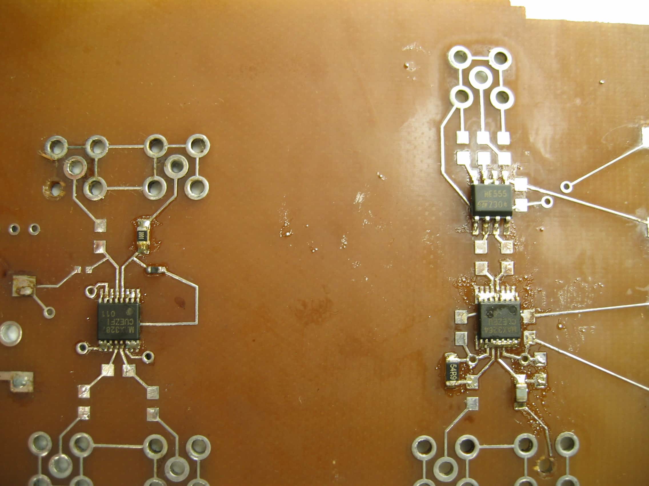
The basic idea of oven reflow is to preset IC’s onto a PCB with solder paste and to heat the paste to its melting point, where the paste begins to “flow” which is why the heating processes containing solder paste is called reflow. During the reflow process, as the solder paste melts and transforms into the shiny solder we’re all familiar with, the surface tension of the molten solder helps center slightly mis-aligned IC’s or components. This makes the reflow process, sometimes, more forgiving than fine tip soldering. The rough steps for reflow using the Cuisinart Toaster Oven are listed below.
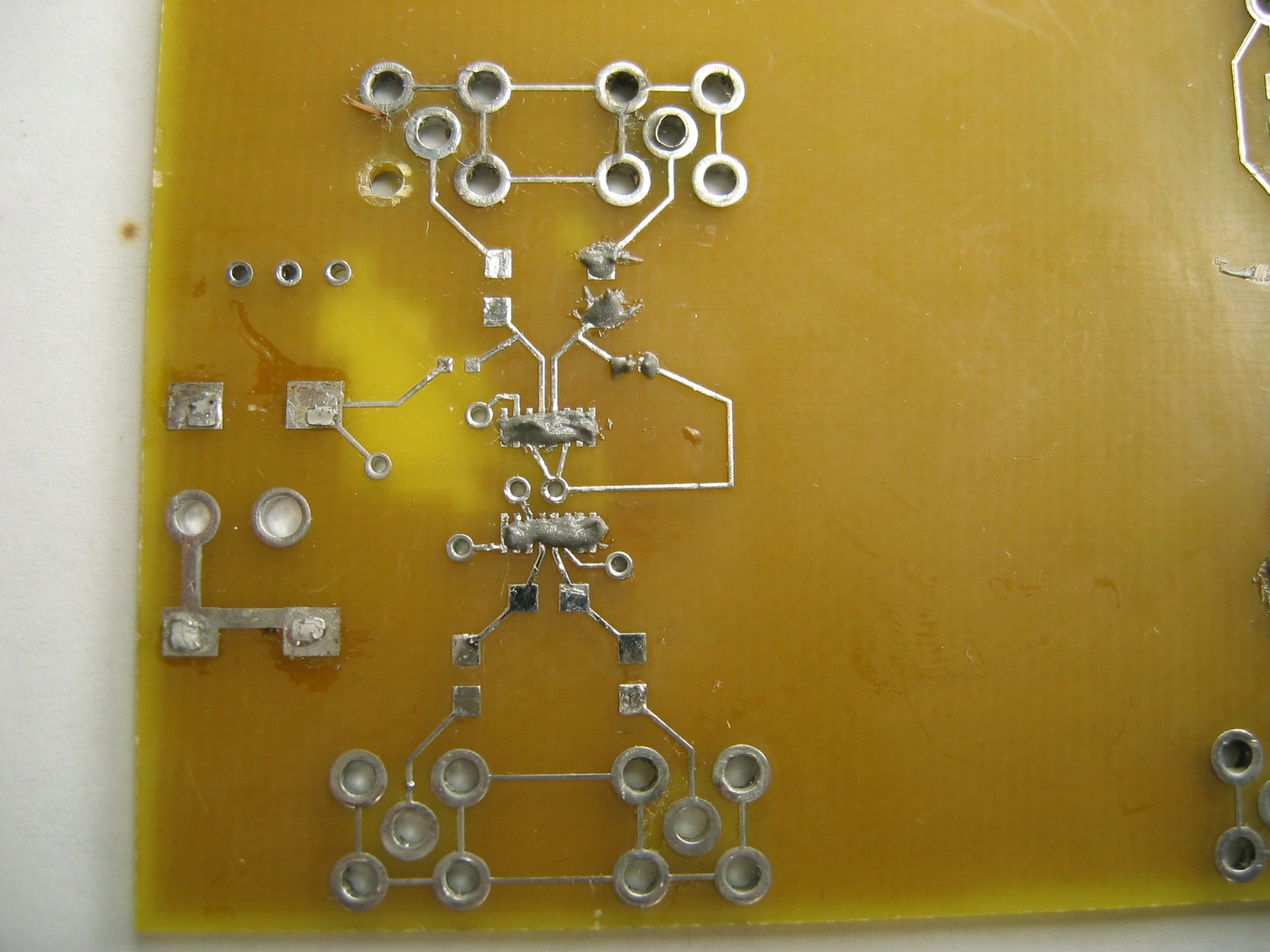
Setting Components
- Click for image
- Apply solder paste carefully, as how well this step is done, directly impacts the end result. Avoid excess use of solder paste, a very small amount will hold the IC in place and achieve an electrical connection. Set components onto solder paste after applying paste to PCB leads taking care to align pins properly.
- Click for image
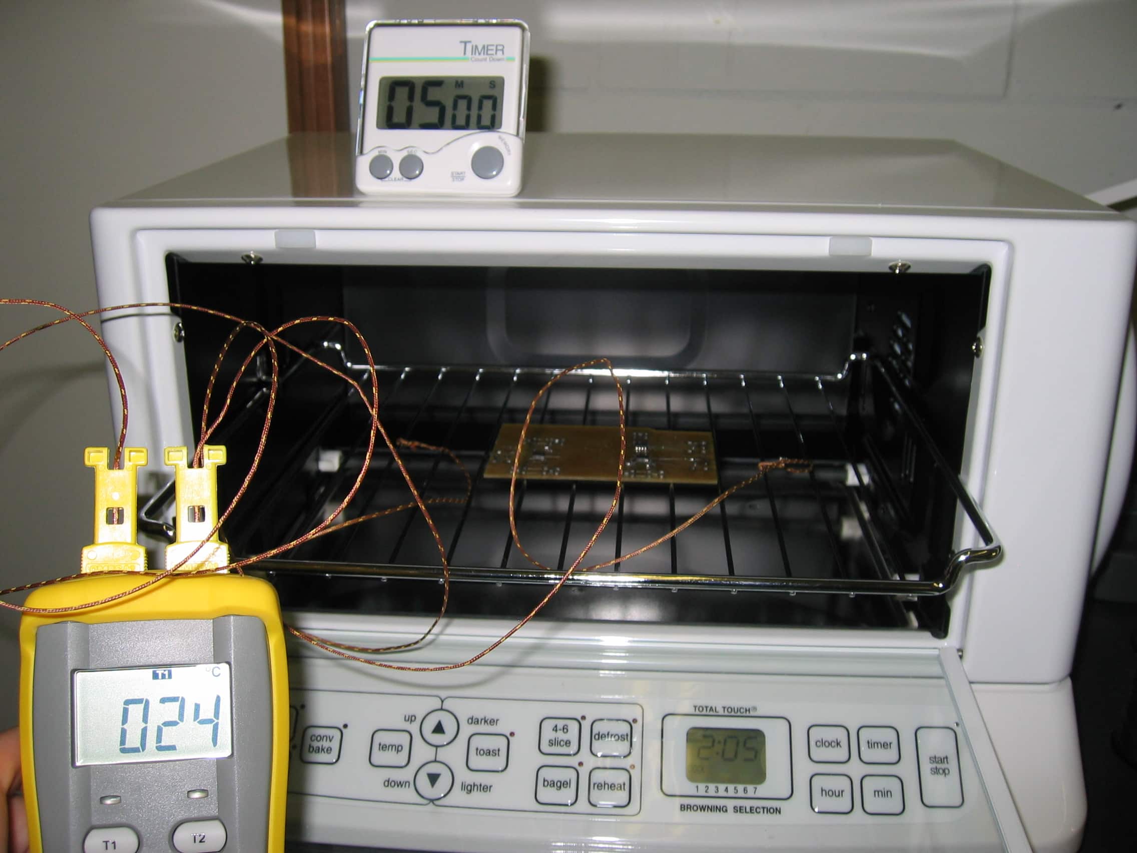
Oven Reflow
- Preheating
- Click for image
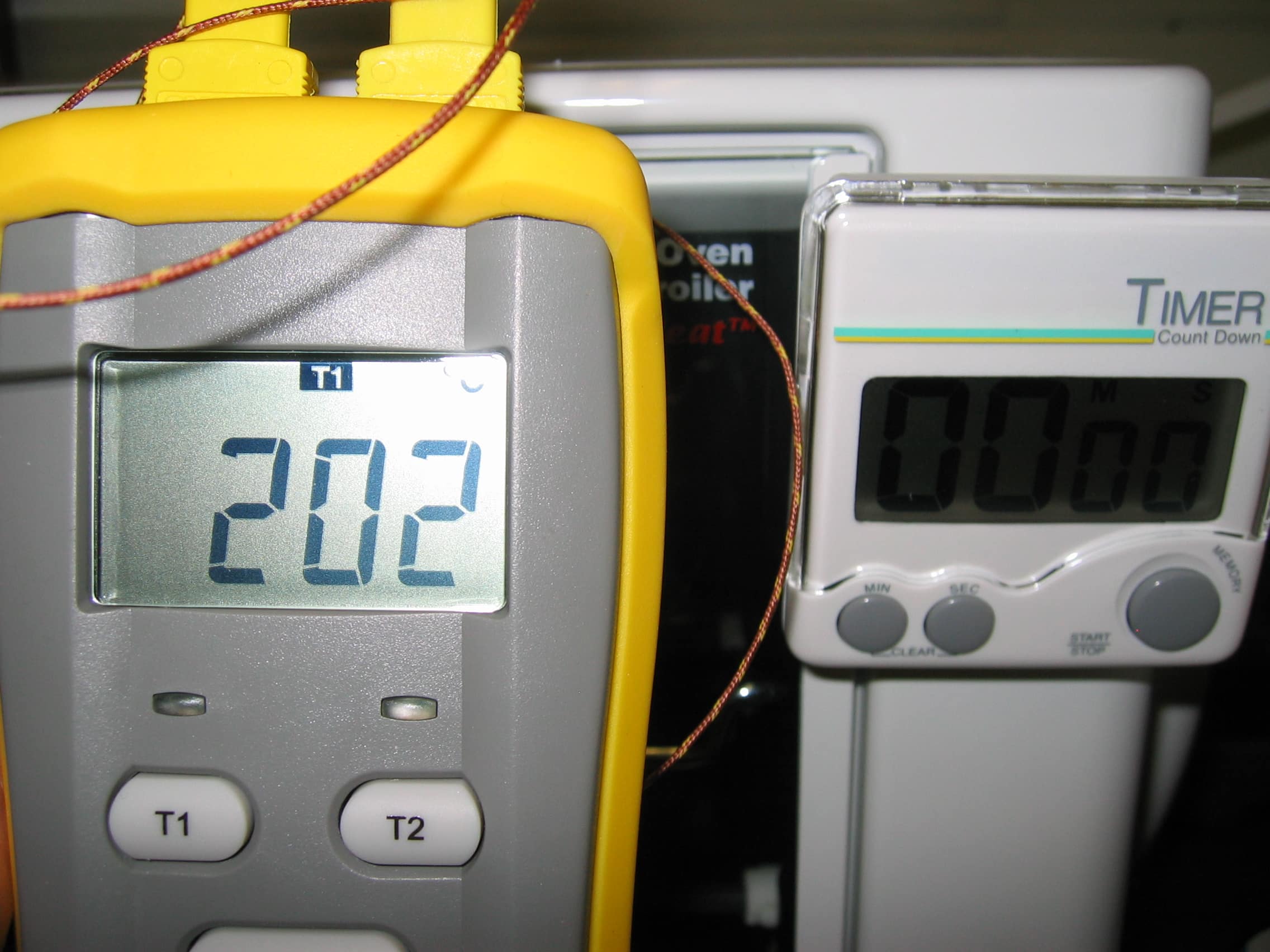
- Set oven to toast 4, press start on oven, and monitor temperature via the thermocouple meter.
- Continue monitoring the thermocouple meter until the temperature reaches ~150-160 degrees Celsius.
- Proceed to Drying phase.
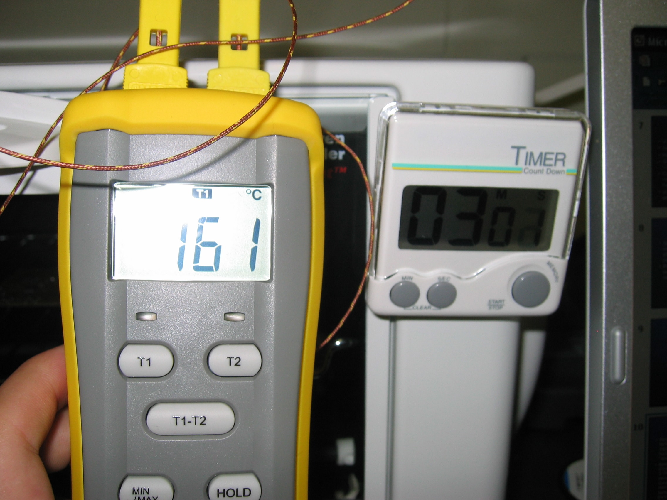
- Drying
- Click for image
- Turn off the oven around 160 degrees for a 1 to 2 min duration, the temperature usually drops to around 150 during that time.
- When the temperature drops to around 145 and about 1:30 has passed, proceed to the Heating phase.
- Heating
- Click for image
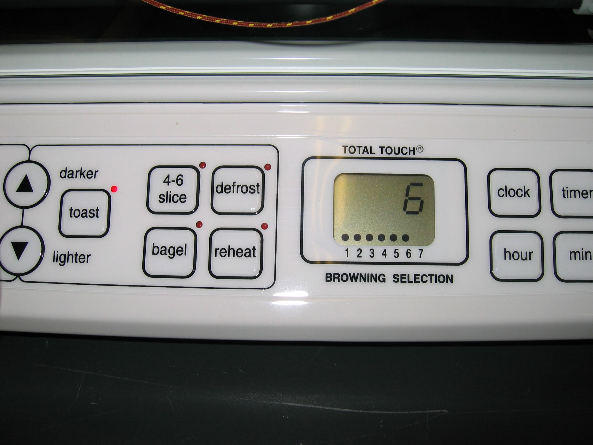
- Set the oven to “toast 6”, press start.
- Once the solder reflow can be confirmed visually or the thermocouple meter reads 200 degrees or higher, turn off the oven.
- Click for image
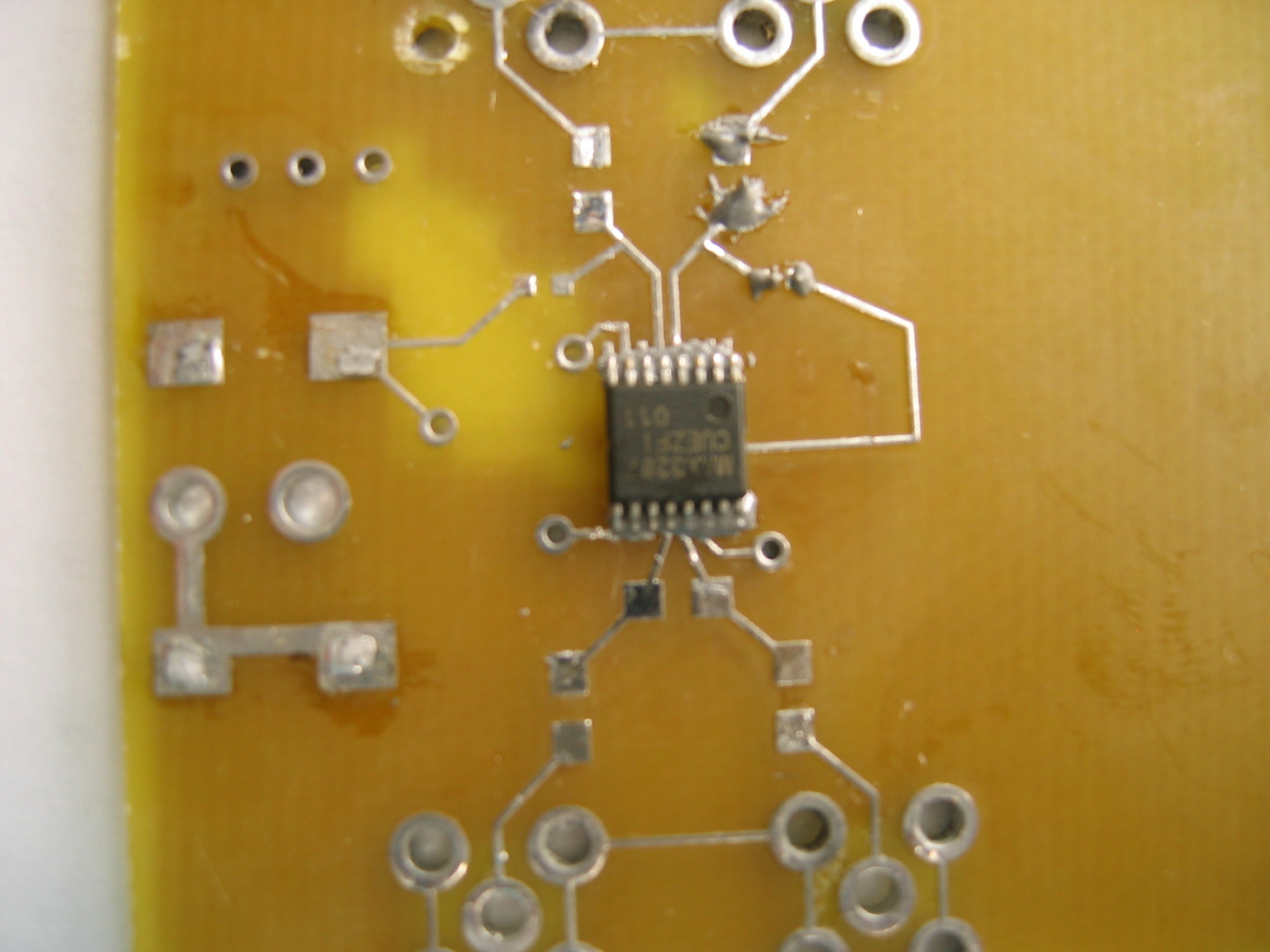
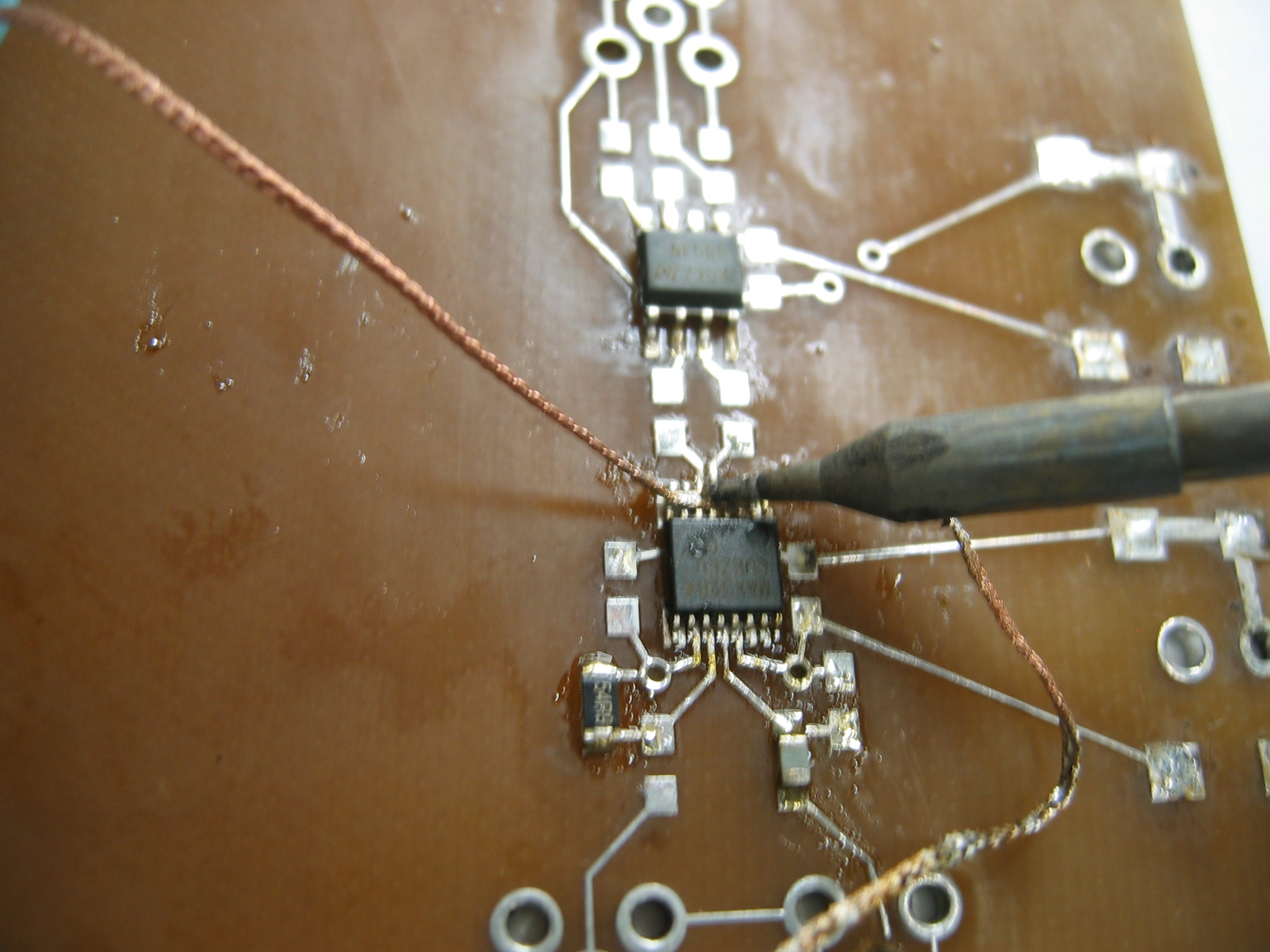
Touch Up
- Click for image
- Merged pins and excess solder can be removed via de-solder braid.
- Check all leads for errors such as shifted pins, and fix as necessary.
- Your SMT circuit should be ready to go!
- Click for image